SmartWave

Text size
+
-

Overview of SmartWave APF

Download

SmartWave APF provides a truly effective harmonic solution with the advanced active harmonic compensation technology.SmartWave APF behaves like a harmonics current generator. It measures the harmonic current generated by nonlinear loads and cancels the harmonics by generating an opposite phase shifted harmonic current with the same amplitude and injecting it to the line, making source current sinusoidal.Besides, SmartWave APF can provide leading or laggard reactive current to improve the power factor.

  • 【Capacity selection】

    SmartWaveAPF产品选型

  • 【The best harmonic solution】

    Recently, power electronic devices are widely applied in electric power equipment, such as uninterruptible power supply, motor driver, arc furnace, trolley car, battery charger, and lighting appliance. The electric power equipment may generate a large amount of harmonic currents due to the nonlinear input characteristic of such loads. The harmonic current will pollute the power distribution system and result in transformer over-heat, rotary machine vibration, degrading voltage quality, and destruction of electric power components and equipment. It is extremely urgent to bring the harmonic pollution under control.

    Active Power Filter (APF) is the most efficient equipment to dispose the power harmonic pollution, enhance the power quality, ensure the safety of the power and equipment, and bring about the green power finally.

  • 【Harmonic and sources】

    When a non-linear load, such as a rectifier, is connected to the system, it draws a current that is not necessarily sinusoidal. Through Fourier series analysis, it is possible to decompose it into a series of simple sinusoids, which start at the fundamental power system frequency and occur at integer multiples of the fundamental frequency. The wave whose frequency is an integer multiple of the fundamental frequency is called harmonic.

    With the increased presence of electronics on power distribution systems, disruptive anomalies are created, and harmonics can become a problem. Typical sources are:

    ● Rectifier devices(electrolysis, electroplate)

    ● AC/DC Variable Speed Drive

    ● DC Power Systems/Chargers

    ● Arc Welding furnace, Induction Heating Equipment

    ● Welding Machines

    ● Electric Training, Marine electric drive

    ● Air condition

    ● Fluorescent Lamps

    ● Uninterruptible Power Supplies (UPS)

    ● Computers and Peripherals

  • 【Harmonic harm】

    ● Harmonic pollution may disturb electrical equipment and systems’ normal operation badly, and causes the following problems:

    ● Over voltage/current in the distribution network

    ● Overheat power cables, transformers, & generators

    ● Overheating in all types of electronics systems causing component failures

    ● Nuisance tripping in circuit breakers and protection relays

    ● Malfunction of automatic control system

    ● Damage to capacitors due to resonance

    ● Inaccuracy of instrument measurement

    ● Interference to telecommunication systems● Interference to telecommunication systems

    ● Voltage distortion and lagging in power factor

  • Main features
  • Working principle
  • Interface
  • Case
  • Fields
  • Specification
  • Link wiring
  • CT connection
  • Parallel wiring
  • Design legend
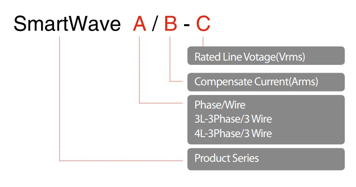
  • Models

Soft-start Resistor Module pre-charges the DC capacitor to avoid from any inrush current while connecting SMARTWAVE to grid initially. When the voltage of the DC capacitor reaches the setting value, the contactor of soft-start module switches on and bypass the pre-charge resistor. Then, the IGBT power converter module start to generate harmonic and reactive current to improve the power factor and eliminate load harmonic. Ripple current filter module filter the high-frequency ripple current from IGBT power converter to avoid high-frequency harmonic pollutions

SmarWave APF has user-friendly control interface which can be easily operated.

With the LCD graphic multifunctional display, users can easily read the electrical date, current and voltage waveform and spectrum, manage the SmartWave APF and monitor the power quality. Users can easily read the information below and operate it in these sections: SmartWave APF, load side and source side:

Voltage, current, frequency, power factor and THD etc.

Waveform and spectrum data (up to the 31st order)

ystem management and parameter setting

Status and alarm, fault

Event Log

SmartWave APF also provides 4 standard relay outputs for remote monitor: power, running, alarm and fault.

A semiconductor manufacturing factory, there are two chip assembly and test plants, and a data analysis center. A lot of low-voltage VFDs, UPS and other non-linear loads are installed in the factory. Equipment can not power off during normal operation, when power-down will result in tens of millions of dollars loss. There are transformers and various protective devices in the power distribution room. During the test run at the factory, transformer overheating and protective equipments malfunction phenomenon is happened. After measured, large 3,5,7,11,13 harmonics are existence and exceed the limits of IEEE519-1992 standard.

After concentrative compensation for the equipments in the workshop of choosing each SmartWave4L/200-400,, the current THD declined significantly and meet the IEEE519-1992 standard. It successfully solved the problems of transformer overheating and protection equipment malfunction to eliminate the huge losses caused by a sudden power outage.

Semiconductor, Metro, Telecommunication, Bank, Hospital, Smart Building, Oil and Gas, Chemical, Power, Mining, Papermaking, Printing, Automobile Manufacture, Oceanic Oil and so on.

The link wiring required by the active power filter includes:

Three power line, connecting to the connecting terminal TB2 or incoming switch (3-phase 4-line APF requires connection with N line) 1 earth line, connecting to the connecting terminal or copper busbar CT output line, connecting to the current signal terminal (TBI)

The loan covers the CT connection to the shunt-wound capacitor bank or inactive power filter

In some application circumstances, if there is any shunt-wound capacitor bank or inactive power filter installed on the site, it should be ensured that the current in the CT test of the user excludes the current of capacitor or inactive power filter.

CT connection and parallel wiring for dual bus tie power supply

At the application site of dual bus tie power supply, it is required to have two sets of CLs, for which the transformation ratio should be ensured consistent and attention should be paid to the CT routing direction.

Smartwave active power filter allows up to 10 sets of equipment running in parallel to increase the compensation capacity. Upon the parallel operation, only a group of CTs are required, and the CT connection is shown as the diagram below (take Phase A as an example). String the outputs at the CT secondary side through the CT connecting terminals on each set of APF. The power lines of each APF are shunted to power grid, and the equipment pieces paralleled are connected via the CAN bus ports on the back of the small screen of the upper computer. The CT connections are shunted.

Copyright © 2015 AUTOWELL All Rights Reserved.

The Honeywell Trademark is used under license from Honeywell International Inc.

Honeywell International inc. makes no representations or warranties with respect to this product [or service].